Project Overview
Allseas was contracted to build a new pipeline to export gas across the black sea consisting of:
- Two 32” pipelines from Anapa, Russia to Kiyiköy, Turkey, with a total length of 925km
- Two micro tunnel pipeline sections on the Russian side
- Two above water tie-ins on the Turkish side
With a rocky substrate that was too hard for trenching, the Turkstream pipeline was laid directly onto the escarpment when transitioning over the continental shelf from 300m to 1100m water depth. The rocky profile resulted in two very challenging freespan locations. The hard shoulders at each end of the spans threatened to induce over stressing in the pipeline during testing and operations.
MMA's Solution
To reduce the pipeline stress, we installed four grouted supports - two at each touchdown point, on either side of the shoulder. The grouted supports used at the upslope locations were our Custom Formworks made with premium woven UV resistant polypropylene. However, due to the sloping seabed, both downslope locations required a complex solution to install the grouted support.
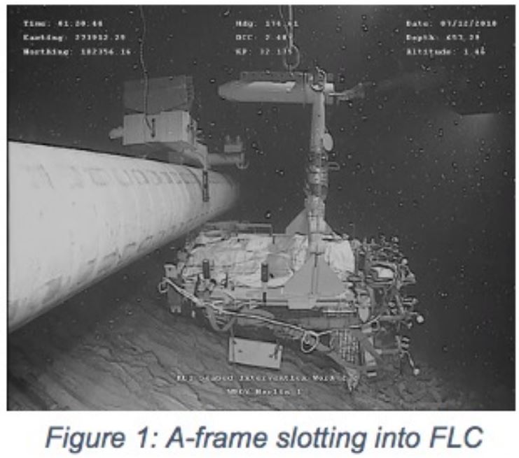
To provide temporary stability of the support, the fabric formwork was integrated into a custom Bag Support Frame (BSF). For contingency stability, the BSFs were attached to a Friction Locking Clamp (FLC) using an A-Frame. The FLC locked onto the pipeline during pouring of the first layers of grout before being removed. IntecSea and Allseas designed the A-Frame and FLC, respectively.
To ensure seamless offshore installation, we performed full-scale System Integration Testing (SIT) at our headquarters in Perth, Australia.
We fitted the FLC and BSF with an inclinometer and bullseye to ensure 4° tolerances were respected during installation and inflation of the formwork.
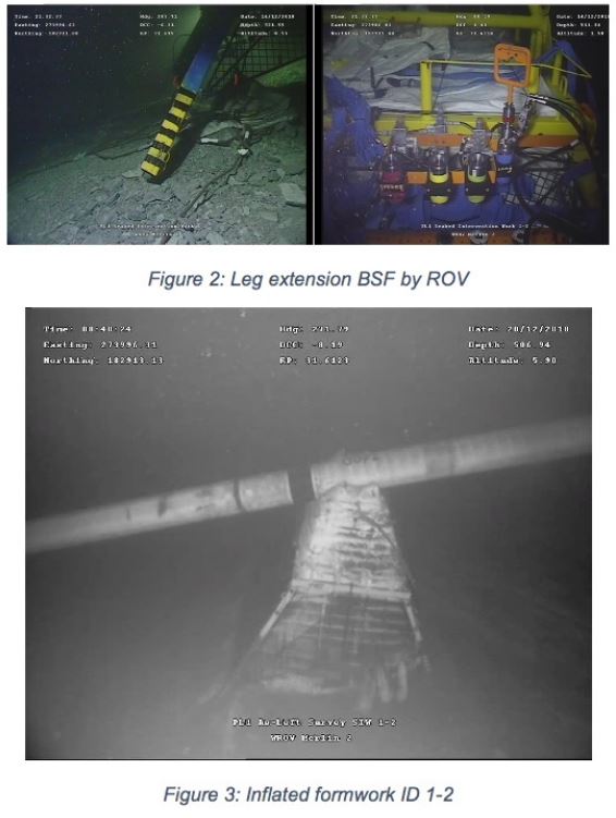
The legs of the BSF were hydraulically actuated by ROV to accommodate any seabed differences from the Digital Terrain Model (DTM). Once the legs were at the correct length, the formworks integrated with the BSF were deployed ready for grouting.
Outcome
Our project process enabled the following outcomes:
- Development of the original concept
- Full-scale System Integration Testing
- Engineering of BSF and bespoke fabric formworks
- ROV friendly design of frames and formworks for installation
- Custom grout design for cold water sour environment
- Design certified by DNV and LOC
Technical Details
| Span ID |
Span Height [m] |
Water Depth [m] |
Slope Port Side [°] |
Slope Starboar |
Slope Starboar |
Formwork Type |
Installation Frame |
| 1.1 |
1,9 |
510 |
16,6 |
19,1 |
4,5 |
Custom |
NA |
| 1.2 |
5,1 |
520 |
19,3 |
33,3 |
31 |
Custom |
ü |
| 2.1 |
1,3 |
651 |
3,1 |
6,1 |
6,5 |
Custom |
NA |
| 2.2 |
3,4 |
660 |
17,4 |
27,2 |
15 |
Custom |
ü |
Key Equipment / Installation Method
- SGM-1000 (grout mixer)
- Friction Locking Clamp
- Bag Support Frame
- A-frame ID 1-2 & A-frame ID 2-2
- BSF ID 1-2 & BSF IF 2-2
MMA Innovation / Value Added
Upon completion of the project, all spans were successfully rectified, with no settlement or sliding observed to supports during our post-installation survey.
Our client was extremely satisfied with the success of the project, stating, “This was one of the most technically complex pipe support issues that Allseas has encountered. The smooth execution is a credit to all parties involved.”